TORSION OF MEMBERS WITH RECTANGULAR CROSS-SECTIONS
Prepared by:
Jeremy Elder
For:
Dr. Mehrdad Negaban
ENGM 325H
April 23rd, 1999
Torsion of members is an important topic in the mechanics of elastic bodies. We can calculate shear stresses and the rotation angles created by applied torques. The study of pure torsion in circular bars is much simplified because of the high degree of geometry in the member. The study of pure torsion in rectangular bars is more in depth. From this report I hope to help create a better understanding of torsion in non-circular members.
Circular members
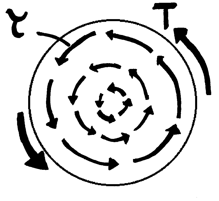
In circular members, central geometry greatly enhances the understanding of torsionís effects. Shear stresses are equivalent along circumfrential lines about the center (see Figure 1.1). Studying pure torsion in circular members and their geometry results in equations (1.1) and (1.2).

Figure 1.1 Shear stress in circular members. Shear stress uniform distributed along circumfrential lines.
t = (rT)/I
p Eq(1.1)Where:
t is shear stress
r is the radius distance from center
T is the applied torque
Ip is the polar moment of inertia
D f = T
l/GIp Eq(1.2)Where:
D f is the change in angle over the length of the bar
l
is the length of the barG is the shear modulus
Rectangular members
The observations made for torsion of members with circular cross sections do not hold for those with non-circular cross-sections:
1. The shear stress is not constant at a given distance from the axis of rotation. As a result, sections perpendicular to the axis of the member warp, indicating out of plane displacement.
2. The theory of elasticity shows that the shear stress at the corners is zero.
3. Maximum shear strain and stress are not at the farthest distance from the rotational axis of a homogeneous non-circular member.
Out of plane displacements require solutions of the non-circular torsion problem to use a warping function. The warping function makes the solution of the problem more complex. We will not explore it here, rather show the results from the first proposed solution to the non-circular torsion problem.
St. Venantís Solutions
St. Venant was the was the first to accurately describe the shear stress distribution on the cross section of a non-circular member using the Theory of Elasticity:
Applicable statements from the theory of elasticity:
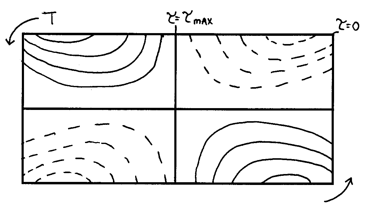
The figures in 2.1 (a) and (b) show St. Venantís resulting stress zones from rectangular and square torsion members.
(a)
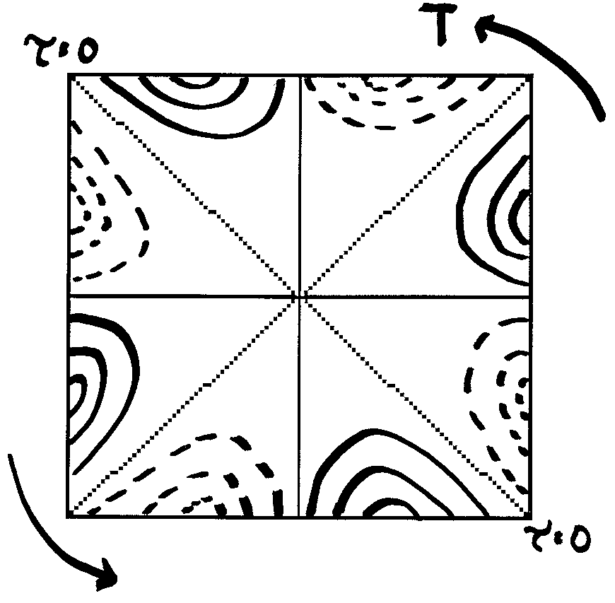
Figure 2.1 (a) shows the resulting stress zones in an rectangular element of b/t = 2, where b is the length of the long side and t is the height. Dashed lines indicate areas of depression and dark lines indicate areas of elevation. St. Venant computed that as the ratio of t/b approaches 1.4513 from higher values the four regions decompose into eight regions like that of the square element shown in figure 2.1 (b) where b/t = 1.
The theory of elasticity has been applied to find analytical solutions for the torsion of rectangular elastic members. Equations for shear stress and angle of twist are stated in equations (2.1) and (2.2).

 Eq(2.2)
b= length of the long side
t = thickness, or width of short side
a ,b = parameters obtained from Table 2.1
Table 2.1
|
b/t |
1.0 |
1.5 |
1.75 |
2.0 |
2.5 |
3.0 |
4 |
6 |
8 |
10 |
¥ |
|
a |
.208 |
.231 |
.239 |
.246 |
.258 |
.267 |
.282 |
.299 |
.307 |
.313 |
.333 |
|
b |
.141 |
.198 |
.214 |
.229 |
.249 |
.263 |
.281 |
.299 |
.307 |
.313 |
.333 |
Elastic Membrane Analogy
The solution to the non-circular torsion problem requires the availability of a warping function. The elastic membrane analogy provides for a much simpler way to find the solution to a this problem. Prandtl, showed that the Laplace equation describing the torsion of an elastic member is identical to that used to describe the deflection of an elastic membrane subjected to a uniform pressure.
The elastic membrane analogy is as follows:
Consider a tube which has the same cross-sectional boundary as the bar. Then a hypothetical membrane is stretched over the tubeís cross-section and internal pressure is applied. The deflected shape of the membrane helps us to understand the stress pattern in the bar under torsion.
The following conclusions are used to help understand the analogy:
1. Lines of equal deflection on the membrane (contour lines) correspond to shearing stress lines of the twisted bar.
2. The direction of a particular shear stress resultant at a point is at right angle to the maximum slope of the membrane at the same point.
3. The slope of the deflected membrane at any point, with respect to the edge support plane is proportional in magnitude to the shear stress at the corresponding point on the barís cross section.
4. The applied torsion on the twisted bar is proportional to twice the volume included between the deflected membrane and plane through the supporting edges.
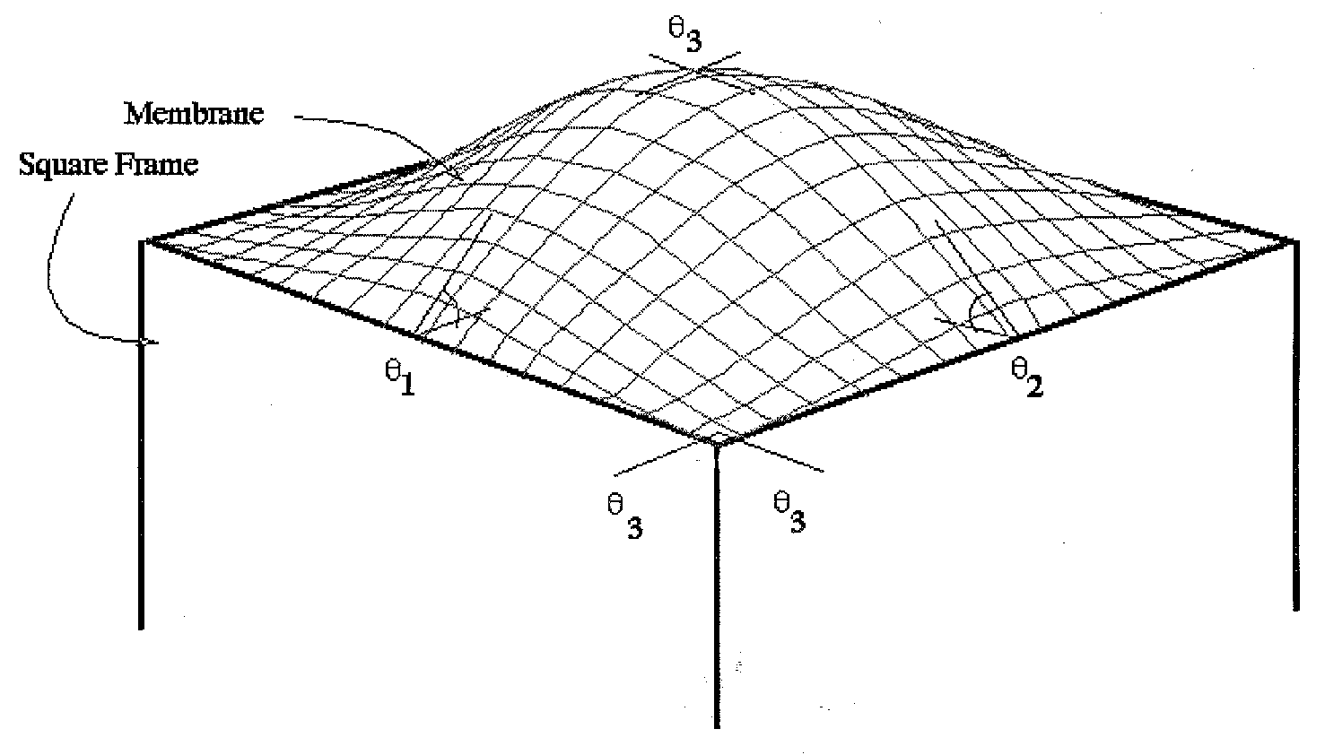
Figure 3.1 Shows the resulting shape of the membrane analogy applied to a square member. q 1 > q 2 , q 3 = 0 (Source: http://ae.msstate.edu/~masoud/Teaching/SA2/A6.5_more2.html)
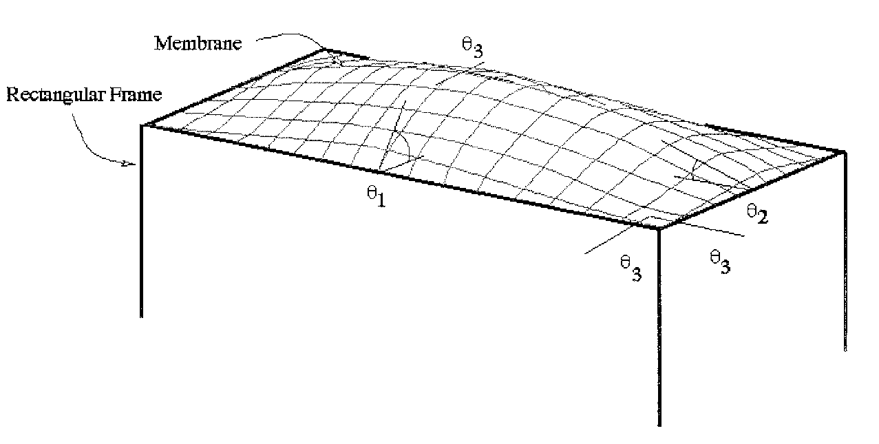
Figure 3.2 shows the resulting shape when applying the membrane analogy to a square member. q 2 = q 1, q 3 = 0 (Source: http://ae.msstate.edu/~masoud/Teaching/SA2/A6.5_more3.html)
In engineering practice most materials are not the ideal, perfect materials we study. In the same way, studying pure torsion in bars of circular cross-section allow understanding of the effects of torque on a member, but many times are exclusive to the situations which arise in the real world. Studying torsion in non-circular structures allows needed calculations to compute the effects of applied torque.
Bibliography
Anniversary volume on applied mechanics, dedicated to C.B. Bienzo by some of his friends and former students on the occasion of his sixty-fifth birthday, March 2nd, 1953. Publisher: Haarlem, H. Stam, 1953.
Basler, K, and C.F. Kollbrunner. Torsion in Structures. New York: Springer-Verlag, 1969.
Heins, C.P. Bending and Torsional Design in Structural Members. Lexington, Massachusetts: Lexington Books, 1975.
http://ae.msstate.edu/~masoud/Teaching/SA2/chA6list.html