The Hole-N-Ator :
An Analysis of the Relation Between the Forces Applied to the Retracted Tissue and the Reactions Applied at the Crank Mechanism
A project for: Engineering Statics (EngM 223)
web page by: Krista Evans
Robert Hohlen, a recent University of Nebraska - Lincoln graduate, is the co-inventor of a new rib retractor that has been used in approximately 20 open-heart surgeries, as of February 1998. Hohlen's device is used for heart valve replacement operations. The Hole-N-Ator, named after Hohlen, was the result of his Agricultural Engineering senior design project. This device allows surgeons to reduce the size of an incision to approximately 1/6 of the previous size. Normally, a 6 x 8 inch incision is made in the chest of the patient, dividing the sternum and opening the entire chest. When using the Hole-N-Ator, however, a surgeon only needs to make a 2 x 4 inch incision and does not need to split the sternum. While the former method used two separate retractors, this new device incorporates both retractors into one stainless steel unit. What makes this new tool so beneficial to surgeons is its ability to retract the chest in two different directions at once. The patient also benefits from the use of this surgical instrument because it reduces pain and discomfort and improves the recovery time, too.
This web page shows the relationship between the forces applied to the retracted tissue of the patient's chest and the force reaction at the crank mechanism of the Hole-N-Ator, by knowing the forces in each rigid-body member, one is better able to understand how this surgical device works. Then, by understanding this relationship between forces and reactions, one could accurately determine the best material to use for the crank mechanism. The information obtained from this relationship could also help to fabricate a similar surgical tool in the future, that would retract tissue with similar forces.
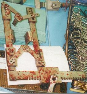
The Hole-N-Ator as shown
here has four retraction points highlighted in pink (2-Fx and
2-Fy).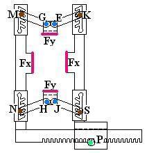
These four retractors are used to retract the muscle and cartilaginous portion of the rib cage without breaking parts of the sternum.
When the Hole-N-Ator is in use, it is cranked open to a certain point and then crank mechanism (P) will self-lock and hold the Hole-N-Ator in place. When it is holding in place it is said to be in equilibrium because all the resultants of the external forces are equal to zero. The static equilibrium definition for a rigid body is that the stationary body will stay static if the resultant force and moment both equal zero. From this statement, one can then express each component of the forces acting on the body equal to zero.
So,
S Fx = 0, S Fy = 0, S Fz = 0 and S Mx= 0, S My= 0, S Mz= 0.
Using these equations, one can find the unknown reactions exerted on each of the rigid bodies comprising the Hole-N-Ator. Reactions within the Hole-N-Ator will not be shown on the free-body diagram of the entire Hole-N-Ator device. In order to analyze the reactions within the rigid body, one must use free-body diagrams of only the rigid bodied subsections of the Hole-N-Ator. Utilizing subsections of the whole free-body diagram will show these internal reactions better than the entire Hole-N-Ator's free-body diagram. This is because when more than one part of a rigid body are analyzed together, the internal reactions are summed and they end up equaling zero. This is because of Newton's Third Law.
Newton's Third Law: The forces of action and reaction between bodies in contact have the same magnitude, same line of action and opposite sense.
In the case of the
Hole-N-Ator, if one wants to see the relationship between the
forces applied to the retracted tissue (Fx and Fy)
and the force reaction at the crank mechanism (Px
and Py), the forces of each subsection's
free-body diagram must be analyzed. The first free-body piece
considered here is the rib blade retractor (the top and bottom
retractors- member GEFy). 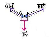 . The force applied to the chest is represented by
the red downward arrow (Fy) and the two blue
forces represent the two-force member reactions (EK
and GM). These two forces (GM
and EK) at an angle q are
assumed to be at a 25 degree angle to the horizontal because that
is what the angle of the pin slots are where the two-force member
connectors are pinned to the side pieces.
. The force applied to the chest is represented by
the red downward arrow (Fy) and the two blue
forces represent the two-force member reactions (EK
and GM). These two forces (GM
and EK) at an angle q are
assumed to be at a 25 degree angle to the horizontal because that
is what the angle of the pin slots are where the two-force member
connectors are pinned to the side pieces.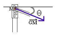 .
.
Thus, for this muscle blade
connector free-body diagram (member GEFy)
S Fx = 0: EK(cos q) - GM(cos q) = 0
EK = GM
S Fy = 0: -Fy + EK (sin q) + GM (sin q)
( substitute EK = GM )
Fy = GM (sin q) + GM (sin q)
Fy/(2 sin q) = GM = EK
This same set of equations can be used to analyze the corresponding members of the bottom (member HJFy) muscle blade connector free-body diagram.
Thus,
GM=EK=HN=JS
Then, the next free-body diagram to be considered is the two-force member called the bar for the muscle blades (member GM).
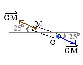
A two-force member has forces that are applied at two points. The two-force member has S F = 0 only if the line of action of the resultant of the forces at the two different points is opposite in direction and equal in magnitude to the other point.
For this free-body diagram, the same force that is acting on it can also be used as the label for the force shown in the opposite direction on the same line of action. In this diagram, GM is used. EK, HN, or JS could also be used.
The next free-body diagram to consider is the entire side piece (member MNP - left side).
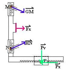
For this left side of the Hole-N-Ator, a few assumptions were made. First, both the top and the bottom muscle blades are considered to have equal and opposite forces (Fy), thereby allowing the two-force members called the bar for the muscle blades (member GM, member EK, member HN, and member JS) to have equal forces applied by them (GM). The reaction being analyzed here are the reactions at the crank (Px and Py). These forces were drawn in an arbitrary direction, and will be defined in the drawn direction or in the opposite direction of the shown force.
Thus, for this free-body diagram,
(remember GM = HN)
S Fx = 0: 2(GM cos q) + Fx - Px = 0
Px = 2(GM cos q) + Fx
S Fy = 0: -GM (sin q) + GM (sin q) - Py = 0
Py = 0
The next free-body diagram to consider is the entire side piece (member KSP - right side).
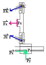
For this right-side of the Hole-N-Ator, assumptions were also made. Again, both the top and the bottom muscle blades are considered to have equal and opposite forces (Fy), thereby allowing the two-force members called the bar for the muscle blades (member GM, member EK, member HN, and member JS) to have equal forces applied by them EK. For the ease of notation, GM is used in this case (remember GM=EK, from above). The reactions at the crank mechanism (Px and Py) are drawn in this free-body diagram, but are drawn in equal and opposite magnitudes in relation to the free-body diagram for the member MNP - left side.
Thus, for this free-body diagram,
S Fx = 0: -2(GM cos q) - Fx + Px = 0
Px = 2(GM cos q) + Fx
(YES! This agrees with above!)
S Fy = 0: -GM (sin q) + GM (sin q) + Py = 0
Py = 0
(YES! This ALSO agrees with above!)
Now that all needed parts have been accounted for in the free-body diagrams above, a relationship between the forces on the blades and the reaction at the crank can be determined. Since Fy/(2 sin q) = GM, it can be shown that for the reactions at the crank mechanism Px depends on both the Fx and the Fy.
Px = 2(GM cos q) + Fx
and
Fy/(2 sin q) = GM
So,
Px = (Fy / sin q) + Fx
and
Py = 0.
The relationship between the forces applied to the retracted tissue and the force reaction at the crank mechanism is found by analyzing the forces of each subsection's free-body diagram. From these equations, it is shown that the x-axis resultant force reaction at the crank (Px) is related to the forces applied by the retracted tissue on the Hole-N-Ator (Fx and Fy). This relation is defined by the equation Px = (Fy / sin q) + Fx. This is a linear relationship between the resultant force on the crank and the forces applied by the retracted tissue, as one of the retracted tissue forces is held constant (either Fx or Fy). One can easily see from this linear equation Px = (Fy / sin q) + Fx, the relationship between the force applied to the retracted tissue of the patient's chest and the force reaction at the crank mechanism of the Hole-N-Ator. This proves that by using the simple equations, such as S Fx = 0, S Fy = 0, one can determine the relationship between forces in each rigid-body member of a device like the Hole-N-Ator.