 Wind-powered
generators are becoming an increasingly important and more affordable sector
of energy production across the world, and it should be no surprise that
their design relies heavily on the study of statics. We will examine
just a few of the ways that statics plays a role in the workings of wind
turbines that might be familiar to us--the two owned by Lincoln Electrical
Systems located north of Interstate 80 on 70th street.
Wind-powered
generators are becoming an increasingly important and more affordable sector
of energy production across the world, and it should be no surprise that
their design relies heavily on the study of statics. We will examine
just a few of the ways that statics plays a role in the workings of wind
turbines that might be familiar to us--the two owned by Lincoln Electrical
Systems located north of Interstate 80 on 70th street.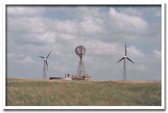
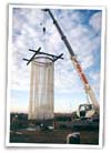
The machines are huge, measuring 213 feet to the top of the tower and a whopping 290 feet to the top of the blades. With a machine this big, ignoring the statics of the system could be devastating and ultimately result in malfunction or, in a worst-case scenario, the machine's collapse and a huge safety risk.
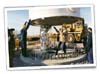
The
machine is composed of three main components: the tower, the blades,
and the nacelle(pictured below)--which sits atop the tower and includes
the gear box, low- and high-speed shafts, generator, controller, and brake. 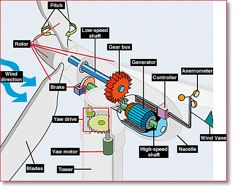
When
the wind blows past the blades, a moment about the central hub is produced.
This is where the power generated by the windmill is developed. There
are numerous other forces, however, and these other forces either directly
counteract the moment about the central hub, or they produce a force directed
along the axis of the central hub. The distribution of the forces
is actually too advanced to be derived using concepts learned in a statics
course, but can be described using some principles of aerodynamics.
A description of some of these aerodynamic principles is available at the
link below:
http://metp02.mw.tu-dresden.de/Merz_McLellan/windenergy/Aero.htm
These
principles give us formulas which can be used to determine some forces
acting on the turbine even if we don't understand how they are derived.
Let us start with a safety question: "Will the tower fall over?". As you can see, this is an important question, and I would like to think that somebody investigated the situation before the tower was built. Let us double check, in case the engineer working on the project was delinquent:
The force exerted on the hub is obtained from the equation for thrust(obtained from the web site listed above--not derived).
Thrust (N) = [(Vup_wind + Vdown_wind)/2]* Dair*Aswept*(Vup_wind - Vdown_wind)...Equation
(a):
Where:
Dair = approx. density of air = 1.29kg./cu.meter
Aswept = area of the turning blades = radius^2*pi
For
our turbines, the radius of the circle formed by the turning blades equals:
radius = 77 ft = 23.47 m
Aswept = 1730.46 m^2
The
maximum thrust for a horizontal axis turbine is when Vdown_wind = Vup_wind/3
(condition for maximum power), and equation (a) then becomes:
Maximum Thrust = Dair*Aswept*(Vup_wind^2)*(4/9)
Wind turbines are controlled to shut down in storm conditions and the overturning moment is principally determined by the maximum output power of the wind turbine. However, providing the output power of the wind turbine can be controlled, the thrust developed is equivalent to maximum power output. The overturning moment can then be obtained by multiplying by the height of the hub above ground level.
For
our turbines, maximum output occurs when the wind speed is:
32.8 miles/hour = 14.66 m/s
Thrust = 1.29*1730.46*(14.66^2)*(4/9) = 213.224 kN
Height of tower = 213 ft = 64.92m
Moment about base = 213.224kN*64.92m= 13,843kN*m
Now
we must determine the moment about the base that the base is able to withstand.
To do this, we must use some information obtained from the Lincoln Electrical
Systems webpage at LES:
Renewable Power: Construction Photos
and LES:
Renewable Power: Questions and Answers.
We find that:
 Circular base = 14 feet diameter = 7 feet radius = 4.2672 m radius
There are 120 anchor bolts that are:
31 feet long = 9.4488 m
200 pounds = 90.718 kg
Using
data obtained from MatWeb.com,
we find that:
 Bolt density = 7.87 g/cc = .01735 lb/cc = 491.297 lb/ft^3 = .00787 kg/cc
Volume of each bolt = 90.718 kg/(.00787 kg/cc) = 11,527.1 cc
Cross-sectional area of each bolt = 11,527.1cc/944.88cm = 12.2 cm^2
Tensile strength of each bolt = (56,500 N/cm^2)*(12.2 cm^2) = 689.271 kN
We
know that there are 120 bolts around the perimeter, but they each contribute
a different moment since they are located at different distances from one
side of the base. The sum of the moments can be calculated as:
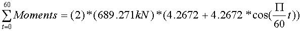 ,
which is a summation of the contribution to the total moment provided by
each bolt. Since each bolt is located a distance of only:
,
which is a summation of the contribution to the total moment provided by
each bolt. Since each bolt is located a distance of only:
Arc distance = (4.2672 m)*2*(pi)/120 = .2234301m
Straight-line distance = .2234045m
from
each other, it is reasonable to assume that they make up a continuous force
which can then be used in an integration. The integration is based
on this assumption and on the following diagram:
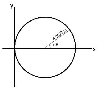
The
integral is thus:
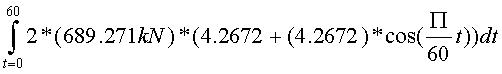
which
evaluates to:
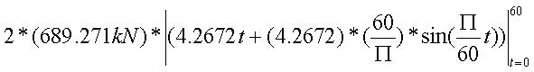
which
equals:
Moment about base that tower can withstand = 352,951 kN*m
As
you can see, the design of the tower anchoring system allows for a safety
margin of:
Safety margin % = (Calculated moment/Maximum
withstandable moment)*100 = (352,951/13,843)*100 = 2,549%
This
is a very acceptable safety margin.
There
is one more thing which we can do using our knowledge of statics, and that
is to calculate the maximum lead of the bolt that will still be self locking.
Using data from http://www.physlink.com/ae139.cfm,we
find that the coefficient of static friction of steel on steel is:
Coefficient of static friction of steel on
steel = .74
and
the maximum lead is calculated as:
radius of bolt = (12.2cm^2/pi)^(1/2) = 1.97
cm
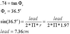
As
you can see, this is a rather large lead, although this lead would be significantly
reduced if there was any lubrication applied(as there frequently is).
However, the safety margin is still adequate, and we can safely conclude
that the design of the wind turbine is sound.