Vibrations of Cantilever Beams:
Deflection, Frequency, and Research Uses
For: Dr. Negahban
EngrM 325H
Scott Whitney
April 23, 1999
Introduction
Measurements of thin film properties are difficult when compared to bulk materials. One method for finding the modulus of elasticity of a thin film is from frequency analysis of a cantilever beam. A straight, horizontal cantilever beam under a vertical load will deform into a curve. When this force is removed, the beam will return to its original shape; however, its inertia will keep the beam in motion. Thus, the beam will vibrate at its characteristic frequencies. If a thin film is sputtered onto the beam, the flexural rigidity will be altered. This change causes the frequency of vibrations to shift. If the frequency shift is measured, the films elastic modulus can be calculated.
Thin Cantilever Beam Setup
Beams studied in this paper are long, thin, cantilever beams. Figure
1, below, shows such a beam. One end of the beam is fixed, while the other
end is free. The origin of the coordinate axis is at the fixed end, point
A.
A typical beam, used in this study, is L = 30 mm long,
w
= 5 mm wide, and t = 0.5 mm thick. The beam material must be chosen
so that its stiffness differs from the thin films stiffness so that the
frequency shift is significant. This study involved zinc oxide films (about
5![]() m thick), so
a good substrate is aluminum.
m thick), so
a good substrate is aluminum.
Figure 1: Typical cantilever beam studied
Deflection of Cantilever Beam
If the free end of a cantilever beam is subjected to a point load, P,
the beam will deflect into a curve. See Figure 2 below. The larger the
load, the greater the deflection, ![]() (x).
(x).
Figure 2: Cantilever beam deflection under load at fixed end
Assuming the beam undergoes small deflections, is in the linearly elastic region, and has a uniform cross-section, the following equations can be used (Gere, p. 602).
The curvature of the beam,![]() ,
is equal to the second derivative of the deflection
,
is equal to the second derivative of the deflection
 (2a)
(2a)
-Determination of Equations
When the force, P, is removed from a displaced beam, the beam will return to its original shape. However, inertia of the beam will cause the beam to vibrate around that initial location. Assuming the elastic modulus, inertia, and cross sectional area (A) are constant along the beam length, the equation for that vibration is (Volterra, p. 310)
Equation (5) can now be written as two differential equations (Volterra, p. 311),
![]()
![]()
The general solution to equation (6a) is a linear combination of trigonometric equations (Volterra, p.312)
 (7)
(7)![]()
Equations (8a) and (8b) can be combined to give
 (9)
(9) (10)
(10)
According to Volterra, p. 312, the constants Cn are arbitrary. However, in order for the dynamic solution for the displacement to be equal to the static solution (at time t=0), C2 must be equal to ½. With this value for C2, Xn(0)=0 and Xn(L)=1.
Plugging equation (9) into either (8a) or (8b) will lead to the frequency equation for a cantilever beam,
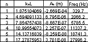
Figure 3: Constants for a cantilever beam vibrations. Note, since cosh(x) is large when x is large, knL needs to be found with high precision.
For each frequency, there exists a characteristic vibration (Volterra, p. 319)
-Examples of Vibration Modes
Typical values of An and frequency (for beams used in this study) are shown in Figure 3, above. Notice that only the first few modes of vibration have significantly large values for the constant An. Thus, the higher order vibration modes can be ignored. To get the total displacement of the cantilever beam, simply add all the displacements found in equation (12) for each mode. Below, Figure 4 shows the displacement caused by each mode at t=0; also included is the total initial displacement of the beam. From these displacements it is apparent that even the third characteristic mode has little effect on the total displacement of the beam.
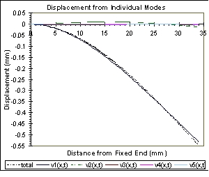
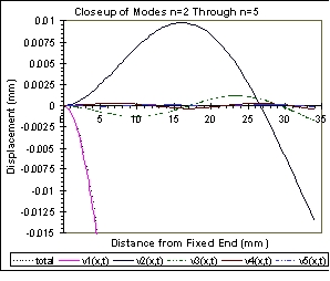
Figure 4: Initial displacement caused by each mode.
As time progresses, each mode will vibrate around the zero displacement line with the frequency listed in Figure 3, above. Figure 5, below, shows this vibration for the first two modes, higher modes act similarly. The total beam motion is complex; each characteristic mode vibrates with a different size, shape, and frequency.
The following files can be downloaded to view an animation of the first few modes and total vibration of a cantilever beam. To view these, the Lotus Screencam Player must be downloaded: Scplayer.exe
Total motion: 325Htot.exe
1st mode:
325h1st.exe
2nd mode:
325h2nd.exe
3rd mode:
325h3rd.exe
4th mode:
325h4th.exe
Figure 6, below, shows a reading from a piezoelectric sensor located near the fixed end of the beam; this sensor shows the interaction of each vibration mode. Also shown is the vibration predicted from equation (12) at that location. The actual and predicted signals are nearly identical; the major difference between them is damping (both viscous and Kelvin-Voigt) of the higher order oscillations in the actual signal.
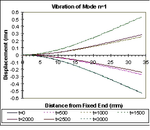
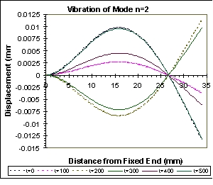
Figure 5: Vibrations of first two characteristic modes; other modes vibrate similarly. Time, t, is in microseconds.
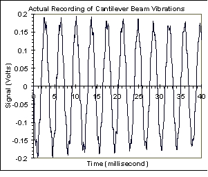
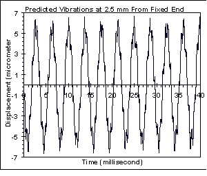
Figure 6: ZnO signal from a vibrating cantilever beam compared to theoretical vibrations.
Measurement of Modulus of Elasticity for Thin Films
-Reason for Using Frequency Analysis
If a cantilever beam is sputter coated with a thin film, then the flexural
rigidity will change. A change in stiffness will directly affect the frequency
of the beams vibrations. Thus, the elastic modulus of the film can be
determined from this frequency shift. See Figure 7 for a schematic drawing
of a sputtered beam; the subscript s refers to the substrate and f
refers to the film. Note, the height of the film is greatly exaggerated,
since ![]() .
.
Figure 7: Cantilever Beam Sputter Coated with Thin Film
Theoretically, the stiffness could be determined from a stationary beam
under a load, P, see equations (2a,b). Suppose the flexural rigidity
was increased by adding a thin film to the beam. Then, assuming the applied
load was constant, the deflection at the free end will decrease. For a
typical beam described above, this displacement change is extremely small.
For example, an aluminum beam with initial displacement (at the free end)
of 0.55 mm will have an initial displacement of 0.49 mm with a relatively
thick (8![]() m) ZnO
film. The 0.06 mm change is too small to be measured with any conventional
tools, and a thinner ZnO film (1
m) ZnO
film. The 0.06 mm change is too small to be measured with any conventional
tools, and a thinner ZnO film (1![]() m)
will give an immeasurable difference in displacement. Thus, stationary
measurements of the films modulus of elasticity are difficult, if not
impossible.
m)
will give an immeasurable difference in displacement. Thus, stationary
measurements of the films modulus of elasticity are difficult, if not
impossible.
However, the same beam coated with ZnO will have its fundamental frequency,![]() ,
shift from 329.7 Hz to 342.0 Hz. Any oscilloscope can be used to measure
the beams vibrations, see Figure 6, above. If enough data points are taken,
a Fourier transform of the signal can measure frequency shifts even as
small as 0.2 Hz. Therefore, the frequency shift can then be known with
high accuracy, and the films elastic modulus can be calculated.
,
shift from 329.7 Hz to 342.0 Hz. Any oscilloscope can be used to measure
the beams vibrations, see Figure 6, above. If enough data points are taken,
a Fourier transform of the signal can measure frequency shifts even as
small as 0.2 Hz. Therefore, the frequency shift can then be known with
high accuracy, and the films elastic modulus can be calculated.
-Determination of Equations
All of the equations derived in the previous sections (1-13) can still
be applied to a two component beam if several of the constants are changed:
EI is replaced with EsIs+EfIf
and![]() is corrected
as shown below. The assumptions stated previously must still be fulfilled:
small deflections, linearly elastic, and uniform cross-section. The latter
assumption implies that the film thickness cannot vary along the beam (difficult
to do when sputter coating long beams).
is corrected
as shown below. The assumptions stated previously must still be fulfilled:
small deflections, linearly elastic, and uniform cross-section. The latter
assumption implies that the film thickness cannot vary along the beam (difficult
to do when sputter coating long beams).
The linear mass density of the coated beam is now
![]()
 (14)
(14)
 (15)
(15)
Conclusion
Due to the small size of thin films, conventional methods of measuring
their properties often do not work. These thin film properties may differ
from the bulk material properties. Therefore, alternative measurement methods
must be developed. Vibration of cantilever beams is one of these methods.
It is not limited to just determining the modulus of elasticity; other
useful information, such as piezoelectric constants, can be determined
from cantilever beams.
Works Cited
Atkins, P. W. Physical Chemistry. 5th ed. New York: W. H. Freeman and Company, 1994.
Gere, J. M., Timoshenko, S. P. Mechanics of Materials. 4th ed. Boston: PWS Publishing Company, 1997.
Voltera, E., Zachmanoglou, E. C. Dynamics of Vibrations. Columbus,
Charles E. Merrill Books, Inc., 1965.