Pure Bending
Kinematics of
pure bending:
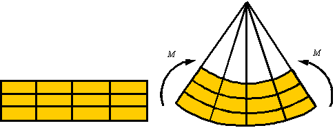
When a bar is subjected to a pure bending moment
as shown in the figure it is observed that axial lines bend to form
circumferential lines and transverse lines remain straight and become radial
lines.
In the process of bending there are axial line that do not extend or contract. The surface descrived by the set of lines that do not extend or contract is called the neutral surface. Lines on one side of the neutral surface extend and on the other contract since the arc length is smaller on one side and larger on the other side of the neutral surface. The figure shows the netral surface in both the initial and the bent configuration.
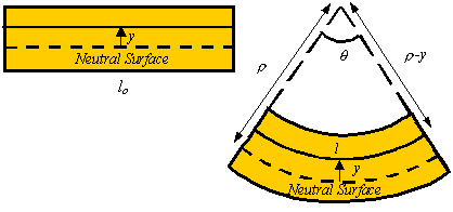
The axial strain in a line element a distance y above the neutral surface is given by
![]()
where r is the radius to the neutral surface.
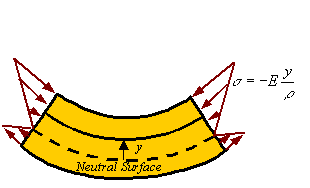
Stress
distribution in pure bending:
By Hooke’s law, the axial stress is
given in terms of the axial strain by the relation
![]()
Therefore,
the axial stress is zero on the neutral surface and increases linearly as one
moves away from the neutral axis.
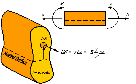
Axial load and
the location of the neutral axis:

There
is zero axial load in a member under pure bending. Therefore, the axial load
generated by the stress should be zero. The axial load ![]() generated by the
stress
generated by the
stress ![]() applied on the area
applied on the area ![]() of the cross section
is given by the approximate relation
of the cross section
is given by the approximate relation
![]()
The
total load on the cross section can be calculated by integrating this relation
over the cross section. This yields
![]()
Since
the axial load is zero during pure bending, one concludes that for pure bending
![]()
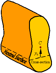
The
reader recalls that the location of the centroid of an area is calculated from
the relation
![]()
Therefore,
for the axial load to be zero, the neutral axis must pass through the centroid of the cross section (i.e., yc=0).
In the event that the axial load is not zero, the location of the neutral axis
relative to the centroid of the cross section can be calculated from the
relation
![]()
Bending moment
and its relation to radius of curvature:
The
bending moment ![]() about the neutral
surface that is created by the normal load
about the neutral
surface that is created by the normal load ![]() resulting from the
normal stress
resulting from the
normal stress ![]() acting on the area
acting on the area ![]() of the cross section
can be calculated by
of the cross section
can be calculated by
![]()
Integrating
over the cross section to get the total moment transmitted through the cross
section gives
![]()
Recalling
that the integral in this relation is the area moment of inertial I
about the neutral axis (the line resulting from the intersection of the cross
section and the neutral surface), the relation between the bending moment M and radius of curvature r
of the neutral axis of the beam becomes
![]()
From this relation one can calculate the expression for stress as a function of the bending moment by substituting in the expression for axial stress this relation for the radius of curvature. This gives

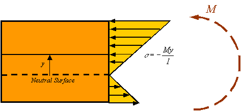
As can
be seen in the figure, the maximum and minimum normal stresses occur in the
material that is furthest away from the neutral surface (either at the top or
bottom of the bar depending on the actual direction of the moment).
ã Mehrdad Negahban and the University of Nebraska, 1996-2000.
All rights reserved
Copy and distribute freely for personal use only
Department of Engineering Mechanics, University of Nebraska, Lincoln, NE 68588-0526