Buckling of Columns
Basic idea:
Consider a column that is constructed from two
pin-connected links with a torsional spring connected between the two links as
shown in the figure. As long as the two bars AB and BC are perfectly aligned,
the system is in equilibrium and one theoretically can increase the load until
the beams fail in compression.
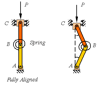
In reality, the two members can never be perfectly aligned so the system supports the load by the aid of the torsional spring and takes a shape such as shown in the right figure above.
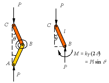
Since
the member ABC is a two-force member, the loads applied at A and C
must be equal and along the line connecting A to C as shown in
the above left figure. The free-body-diagram of AB shown on the right side of
the figure above indicates that for equilibrium to hold, the miss-alignment
angle ![]() must increase until
the moment in the torsional spring increases to balance the couple developed by
the two vertical forces. This requires that
must increase until
the moment in the torsional spring increases to balance the couple developed by
the two vertical forces. This requires that
![]()
where
kT is the stiffness of the torsional spring and the reader
notes that the torsional spring is twisted twice the miss-alignment angle ![]() . Assuming small miss-alignment angles so that one can
replace
. Assuming small miss-alignment angles so that one can
replace ![]() by
by ![]() , one gets
, one gets
![]()
Obviously,
![]() is a solution to this
equation. This solution represents the trivial solution that reflects the
perfectly aligned system. But, this system has a non-trivial solution where the
term in the parenthesis becomes zero to require
is a solution to this
equation. This solution represents the trivial solution that reflects the
perfectly aligned system. But, this system has a non-trivial solution where the
term in the parenthesis becomes zero to require
![]()
The
load calculated in this way is called the critical load, designated by the
subscript “cr”. For loads smaller than the critical load, the system will have
accelerations that are consistent with bringing the system back into alignment.
For loads above this critical load the system has accelerations consistent with
increasing the miss-alignment angle, resulting in the collapse of the system.
Therefore, the system is considered to be capable of carrying loads up to the
critical load.
Buckling in a
simply supported column:
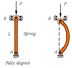
Consider the
pin-connected column AB of length L as shown in the following
figure. Similar to the example above, if the column is fully aligned, the
applied compressive load P can be increased until one reaches the
compressive strength of the material. Yet, in reality the column will fail due
to buckling as shown in the figure on the right long before this load is
reached.
The analysis of the buckling of a continuous column is
similar to the example given above to motivate the problem. Since the column is
a two-force member, the reaction loads at the two pins are equal and directed
along the line connecting the two pins as shown in the figure to the left
below. The free-body-diagram of a segment of the column is also drown below and
it is clear from this diagram that for the member to be in equilibrium the
bending moment must balance the couple created by the misalignment of the two
loads.
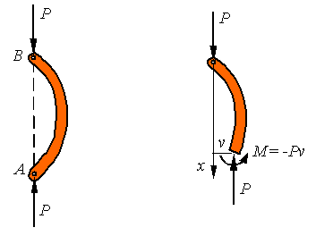
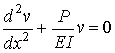
Designating the
out of plane displacement of the column by v, the bending moment must be
M=-Pv. One can combine this with the beam deflection equation

to get the equation for the column as
This is a second
order homogeneous ordinary differential equation with constant coefficients
that has a solution of the form
![]()
where C1 and C2
are constants to be fit to the boundary conditions and ![]() must be restricted to
satisfy the differential equation. The boundary conditions for this
pin-supported column are that the displacement is zero at both supports.
Therefore,
must be restricted to
satisfy the differential equation. The boundary conditions for this
pin-supported column are that the displacement is zero at both supports.
Therefore,
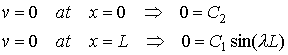
Obviously, if both C1 and C2
are zero one obtains the trivial solution v=0 for the fully aligned
beam. For the beam to have a nontrivial solution (buckled solution), one must
select ![]() that results in
requirement that
that results in
requirement that ![]() that yield
that yield
![]()
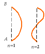
for any integer n. This results in the
solution
![]()
As can be seen
from the figure, different values of n represent different modes of
buckling.
In addition to the boundary conditions, the solution
must satisfy the differential equation. Substitution of this solution into the
differential equation gives
![]()
Reorganization yields
![]()
Clearly, if C1 is zero, one arrives at
the trivial solution v=0 that satisfies the differential equation, and
which is associated with the fully aligned beam, but there is a non-trivial
solution when the term in the round parentheses goes to zero. Therefore, to get
a nontrivial solution to the buckling problem, the axial load must satisfy the
relation
![]() , which results in the expression for the critical load given
by
, which results in the expression for the critical load given
by
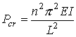
Obviously, the smallest critical load is associated
with n=1. Therefore, the column will buckle at the load associated with
the first buckling mode if the column is not restricted from taking the shape
associated with this mode.
Different
supports:
The
buckling of columns with a variety of different support conditions are shown in
the following figure and can be analyzed using similar procedures to the simply
supported column studied above.
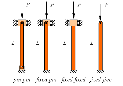
The
results for the other columns are similar to the pin-pin supported column
analyzed above with only the replacement of the actual length of the column
with an effective length. If L is the actual length of the column and Le
is the effective length of the column, then the critical buckling load for the
column is given by
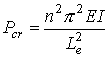
where the effective length Le is given by
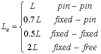
![]()
ã Mehrdad Negahban and the University of Nebraska, 1996-2000.
All rights reserved
Copy and distribute freely for personal use only
Department of Engineering Mechanics, University of Nebraska, Lincoln, NE 68588-0526
Last modified at: 5:32
PM,
Monday, November 27, 2000