by Zach Dunbar
Statics 223 H (Fall 2000)
by Zach Dunbar
Statics 223 H (Fall 2000)
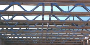
A truss
is
a complicated and potentially frustrating statics problem to solve. The
more members a truss contains, the longer it takes to solve. It can be
overwhelming to attempt to solve these trusses via the method
of joints. Using the method of sections, this process can be
sped up a great deal, but it requires a good deal of thought to figure
out where to begin, and how to proceed.
A way around this is to utilized the
power of computers to assist in the computation of the method of joints.
Since this method is a fairly straight forward and mindless task, the computer
can perform these masses of computations quicker and more accurately (and
with less frustration) than a person. Therefore, it would be useful
if there where a computer program to perform these operations for you.
The method my program will use for determining the forces in a truss member is as follows:
I. The program will receive input from the user regarding the various components of the truss, such as
A. the coordinates of the vertices
B. the loads at those vertices
C. which vertices are connected
to one another by various members.
II. The program will then use the input data to determine the loads in each of these members.
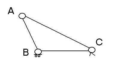 A simple example of a truss that this program will evaluate is the one
shown at left. It consists of several vertices, one of which is a
hinge (vertex C, exerting forces only in the X and Y direction) and another
which is set on rollers (vertex B, exerting forces only in the Y direction)
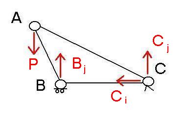
as shown in the free body diagram below.
A simple example of a truss that this program will evaluate is the one
shown at left. It consists of several vertices, one of which is a
hinge (vertex C, exerting forces only in the X and Y direction) and another
which is set on rollers (vertex B, exerting forces only in the Y direction)
as shown in the free body diagram below.
The Program
Once the forces in these first 2 members are solved, we move on to another vertex which has only two unknown member forces, and solve for these forces in a similar way. Then we simply repeat this process until all the members of the truss have been found. Complications arise when a vertex has more than just 2 members attached to it, and if the force on the vertex is in any direction besides the vertical. This is the none computer code explanation of what the program is doing to find this information. For a full computer code explanation of how I programmed the program, please download the source code available at the bottom of this page.
Equations
# of members =(2*#of vertices-3)
Force B=Force A/sin theta; if F is some vertical
force and B is some angled force, and there are no other vertical forces
at the joint.
Force C = Force B*cos phi; if FC is the purely
horizontal member that is attached to the same point as B, and phi is the
angle between them.
DX=X2 /X1;
DY=Y2 /Y1;
a2 + b2 = c2
 All the force at the various vertices are required before the program can
be successfully run. However, these forces can be calculated manually,
using various mathematical techniques. This is not an overall limitation
to computer aided truss calculation, but merely a limitation in my programing
skill.
All the force at the various vertices are required before the program can
be successfully run. However, these forces can be calculated manually,
using various mathematical techniques. This is not an overall limitation
to computer aided truss calculation, but merely a limitation in my programing
skill.
The limitations of the program are as follows:
| The forces at all the vertices must be known. | Why? |
| The user must have a good knowledge of the physical layout of the truss structure, i.e. the coordinates of each vertex. | Why? |
| If the force isn't given for a particular vertex, the user must have the necessary skills of how to calculate it. | Why? |
| The truss must be of a limited number of members, only a 3 member truss can be calculated using this program. | Why? |
| The forces applied at the vertices most be applied only in the vertical direction, not horizontal or at an angle. | Why? |
All of these program limitations aren't set in stone. With sufficient time and programming skill, all of them could eventually be overcome, and a truss program could be written what could solve any type of mathematically solvable truss problem.
The following are available for user download: